Audio processing is a fascinating and essential area in embedded systems, where hardware meets the real world in the most tangible way—through sound. Whether it's enhancing voice recognition in smart devices, filtering noise in automotive systems, or creating immersive audio experiences in consumer electronics, audio processing is at the heart of many cutting-edge applications.
For embedded engineers, mastering audio processing opens up a world of opportunities. But unlike software engineers working in high-level languages, embedded engineers face unique challenges: constrained hardware resources, real-time processing demands, and the need to optimize every bit of memory and every clock cycle.
This blog series is designed to bridge the gap between theory and practical implementation, providing you with the foundational knowledge and hands-on techniques needed to tackle audio processing in embedded systems. We'll explore key concepts like digital signal processing (DSP), filter design, noise reduction, and more, all with a focus on the specific needs of embedded environments.
Whether you're new to audio processing or looking to deepen your expertise, this series will equip you with the tools and insights to bring high-quality audio solutions to your next embedded project. Let’s dive into the world where sound and silicon meet!
Let's first understand
how a speaker works. Please watch this video .
how a class D amplifier works. Please watch this video .
Here's a brief description of some points we need to understand before starting the actual audio applications:
PWM (Pulse Width Modulation):
Audio is encoded by varying the width of the pulses within a fixed period, where pulse width is proportional to the audio signal's amplitude. Often used in Class-D amplifiers.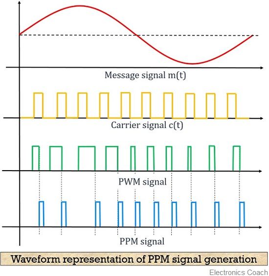
PPM (Pulse Position Modulation):
Encodes audio by varying the position of each pulse relative to a reference point. Less common in audio but used in certain communication systems.PDM (Pulse Density Modulation):
Represents audio as a 1-bit stream where the density of pulses (1s) corresponds to the signal amplitude. Common in digital microphones and some DACs.I2S (Inter-IC Sound):
A serial bus standard for transmitting PCM audio data between digital audio devices. Widely used for connecting processors to DACs and ADCs.PCM (Pulse Code Modulation):
Encodes audio as a series of multi-bit samples representing the signal amplitude at each point in time. Standard format for digital audio in CDs, computers, and streaming.
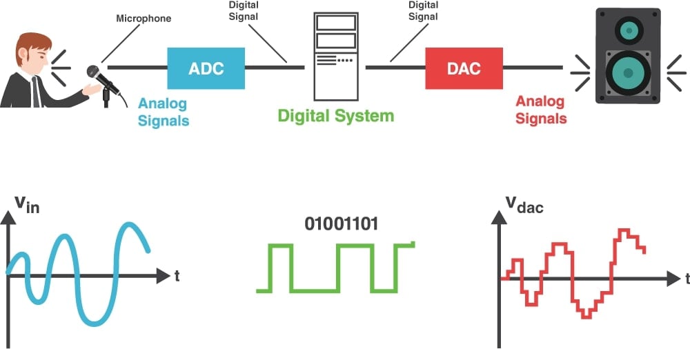
DAC Signal (Digital-to-Analog Converter Signal):
The output of a DAC, which converts digital audio signals (PCM, PDM, etc.) into a continuous analog signal that can drive speakers or other analog audio equipment. Below image is very simplified version as it does not include the amplifier right before the speaker in the diagram.
Now let's look some of them in a bit details
Pulse Density Modulation (PDM)
is best understood as "oversampled 1-bit audio." It's a simple digital system that uses a very high sampling rate with just one bit per sample. If you took the 16-bit audio of a CD, dramatically increased its sampling rate, and reduced the wordlength to 1 bit in a sensible way, you'd have a PDM system. PDM is more straightforward than Pulse Code Modulation (PCM).
PCM (Pulse Code Modulation):
- Sampling Rate: Determines the system's bandwidth (how much of the audio spectrum it can capture). The bandwidth is half the sampling rate (fs/2).
- Wordlength: Determines the Signal-to-Noise Ratio (SNR), which is calculated as dB, where is the number of bits.
In contrast, PDM simplifies by using just one bit and a much higher sampling rate.
Noise Shaping in 1-Bit Audio Systems
When converting a 24-bit PCM signal to a 1-bit system like PDM, directly reducing the wordlength by keeping only the Most Significant Bit (MSB) creates severe distortion—over 40%. This happens because the system lacks dithering, which is crucial for managing quantization errors.
Dithering is a process that adds a small amount of random noise before quantization. This noise helps to decorrelate the quantization errors from the signal, turning them into a uniform white noise floor rather than distortion. Without dithering, these errors align with the signal, causing unpleasant artifacts.
Noise shaping improves 1-bit audio by redistributing the quantization noise into higher frequencies, where it is less audible. This allows for a more accurate representation of the original signal, even with only 1 bit per sample.
Oversampling Reducing wordlength in digital audio introduces significant noise, especially when dropping to 1-bit, which can be up to 90 dB noisier than a 16-bit system. Noise shaping can push this noise to higher frequencies, which works well in imaging but not in audio, where mid- and high-frequency noise is very noticeable.
To manage this, a higher sampling rate is used. This increases the system's bandwidth, allowing noise to be shifted above the audible range, where it can't be heard. There are two ways to achieve this higher sampling rate:
- Direct High Sampling Rate: Used in PDM microphones with rates around 3 MHz.
- Interpolation: Used in DACs and systems that convert PCM audio to PDM, where the original sampling rate might be as low as 48 kHz.
how does a PDM modulator decides which bit is going to be 1 and which one is 0?
A PDM modulator decides whether to output a 1 or 0 based on the cumulative error between the original analog signal and the modulated digital signal.
Here's how it works:
Integration and Comparison:
- The analog input signal is continuously integrated (accumulated over time).
- At each sampling interval, the integrator's output is compared against a threshold, usually set to zero.
Bit Decision:
- If the integrator's output is above the threshold, the modulator outputs a
1. - If it is below the threshold, the modulator outputs a
0.
- If the integrator's output is above the threshold, the modulator outputs a
Error Feedback:
- After deciding the bit, the modulator subtracts the equivalent of the digital output (either +1 or -1) from the integrator's output. This creates an error signal that is fed back into the system, ensuring that the modulator keeps track of the cumulative difference between the desired analog signal and the generated digital output.
Noise Shaping:
- The feedback mechanism shifts the quantization error (the difference between the actual analog signal and the 1-bit output) to higher frequencies. This reduces the error in the frequency range of interest (usually the lower frequencies for audio), making the noise less audible.
The result is that the PDM modulator outputs a stream of 1s and 0s where the density of 1s is proportional to the amplitude of the input signal. For more info on PDM and PCM visit this document.
Let say I have two signals one is PWM + LPF and other I have is DAC output signal, which one's quality will be good for a speaker application?
Is it okay to drive a speaker with one of the above DAC/PWM+LPF signal or we should have a Class-D amplifier in place?
It is generally not advisable to drive a speaker directly with either a DAC output signal or a PWM+LPF signal without amplification. Here’s why a Class D amplifier is recommended:
Power Levels:
- DAC Output Signal: The signal from a DAC is a low-power analog output designed for line-level audio (e.g., 1-2 volts peak-to-peak). It lacks the power needed to drive a speaker, which typically requires tens to hundreds of watts.
- PWM+LPF Signal: While a PWM signal can be converted to an analog signal using an LPF, it still lacks the necessary power to drive a speaker directly. The signal is usually low-power and needs amplification to achieve the required speaker drive levels.
Impedance Matching:
- Speakers have low impedance (typically 4-8 ohms), which demands more current than a DAC or unamplified signal can provide. A Class D amplifier is designed to match this impedance and deliver the necessary current without damaging the DAC or other components.
Efficiency and Quality:
- Class D amplifiers are highly efficient and can amplify both DAC and PWM signals effectively with minimal power loss as heat. They are specifically designed to drive speakers, offering both the necessary power and maintaining audio quality.
Conclusion: To properly drive a speaker with good sound quality and sufficient volume, a Class D amplifier is necessary. It ensures that the signal (whether from a DAC or PWM+LPF) is amplified to the appropriate power level, matches the speaker’s impedance, and delivers clear, undistorted audio.
Possible Class-D amplifier input interfaces
Class D amplifiers can accept various types of input interfaces, each suited to different applications and signal types. Here’s common Class D input interfaces:
Analog Input:
Description: Receives a continuous analog signal directly from sources such as DACs.
Usage: Often used in audio amplifiers where the input signal is in standard analog form (e.g., from a CD player or a preamp).Digital Input:
Description: Accepts digital audio signals directly, often in formats like I2S, SPDIF, or TDM. The Class D amplifier typically includes a built-in digital-to-analog conversion stage.
Usage: Used in digital audio systems where the amplifier integrates with digital sources, reducing the need for external DACs.Pulse Width Modulation (PWM) Input:
Description: Accepts PWM signals directly. Class D amplifiers designed for PWM inputs process these signals without needing additional conversion.Pulse Density Modulation (PDM) Input:
Description: Some Class D amplifiers accept PDM signals directly. PDM signals are typically converted internally to a form suitable for amplification.
Usage: Seen in specific applications, particularly where PDM is used, such as in some digital microphones.Differential Input:
Description: Receives a differential signal, which can help reduce noise and interference by using a balanced input configuration.
For example: XPT8871 Class D amplifier supports differential analog inputs for high-quality audio, with an option for single-ended input and internal gain control. That means options-1,3+LPF,5 can be used as input signal source to this IC.
XPT8871 Example Schematics

A video on designing the Amplifier circuit: Link
An excellent video on understanding the Class D-Amplifier: Link, this video explains how PWM can be used to generate amplified output signal of input shape.
In depth understanding of Class-D Amplifier
This is an audio source for the amplifier.


Now it's time to zoom out this

Zoom again

Zoom again

Zoom again

Zoom again and you will see a 2Hz signal at the LPF filter output that amplified.

Now it's time to remove the almost 6V of DC offset from the LPF filtered signal, it will be ready to feed to the Speaker.

Comments
Post a Comment