This post is planned for controlling the low power BLDC/PMSM motors using FOC algorithm. But, the FOC algorithm itself is a huge and complex topic to discuss. Hence, at first very simple motor with easy algorithm are discussed, and based on the understanding, gradually more advanced topics will be discussed such as FOC.
Introduction

To be updated!
Controlling A2212/13T 1000KV BLDC motor with Arduino Uno and Simonk 30A
Code
Waveform to Motor


To be updated!
Introduction to SimpleFOC project
To be updated!
ESC controller using L6234
To be updated!
Open Loop Control of A2212/13T 1000KV BLDC using SimpleFOC library and L6234 driver
Code
Remember there are two changes that need to be made, in order for the motor to work well. First, get the pole pair number of your motor. Secondly, find the pins for L6234 pin-out config and enable, and current sensor for phase A and phase B pins config.
// Open loop motor control example
#include &lgt;SimpleFOC.h&rgt;


// BLDC motor & driver instance
// BLDCMotor motor = BLDCMotor(pole pair number);
BLDCMotor motor = BLDCMotor(7);
// BLDCDriver3PWM driver = BLDCDriver3PWM(pwmA, pwmB, pwmC, Enable(optional));
BLDCDriver3PWM driver = BLDCDriver3PWM(5, 9, 6, 8);

// current sensor
// shunt resistor value = 0.01
// gain value = 50
// pins phase A = A0,B = A2, (C optional)
InlineCurrentSense current_sense = InlineCurrentSense(0.01, 50.0, A0, A2);


//target variable
float target_velocity = 0;

// instantiate the commander
Commander command = Commander(Serial);
void doTarget(char* cmd) { command.scalar(&target_velocity, cmd); }

void setup() {

  // initialise the current sensing
  current_sense.init();

  // for SimpleFOCShield v2.01/v2.0.2
  current_sense.gain_b *= -1;

  // driver config
  // power supply voltage [V]
  driver.voltage_power_supply = 12;
  driver.init();
  // link the motor and the driver
  motor.linkDriver(&driver);

  // limiting motor movements
  motor.voltage_limit = 3;   // [V]
  motor.velocity_limit = 5; // [rad/s] cca 50rpm

  // open loop control config
  motor.controller = MotionControlType::velocity_openloop;

  // init motor hardware
  motor.init();

  // add target command T
  command.add('T', doTarget, "target velocity");

  Serial.begin(115200);
  Serial.println("Current sensor ready.");
  Serial.println("Motor ready!");
  Serial.println("Set target velocity [rad/s]");
  _delay(1000);
}

void loop() {

  // open loop velocity movement
  // using motor.voltage_limit and motor.velocity_limit
  motor.move(target_velocity);

  // user communication
  command.run();

  PhaseCurrent_s currents = current_sense.getPhaseCurrents();
  float current_magnitude = current_sense.getDCCurrent();

  Serial.print(currents.a*1000); // milli Amps
  Serial.print("\t");
  Serial.print(currents.b*1000); // milli Amps
  Serial.print("\t");
  Serial.print(currents.c*1000); // milli Amps
  Serial.print("\t");
  Serial.println(current_magnitude*1000); // milli Amps
}
PWM worforms to L6234
3 PWM waveforms generated from Arduino uno development board using above code, is shown below. These PWMs are then fed to the L6234 driver, as a result L6234 generates the waveforms for the motor. Moreover, these two figures have pulse width modulated waveform that in-turn generates the SPWM(sine wave pulse width modulation)
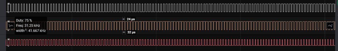 |
| PWM signals at 31.25kHz frequency |
 |
| Zoomed-out version, phase and Arduino pin numbers are mentioned as well |
Waveform to Motor
 |
| waveforms when RPM = 1250 |
 |
| Waveform when RPM = 600 |
Questions to be answered
- My motor is running perfectly well, but L6234 heats up, why?
- L6234 heats up to 60 degrees of surface temperature, but it seems too much of temperature. Because the RPM of motor when the temperature is measured is 1054 at 4.6v.
- Tj = 150 degrees, Rtheta,jA = 1.5 degress/W, Ptot = 2.3W at Tamb = 75 degrees (refer datasheet.
- Tj(calculated) = Tcasetemp+(Rtheta,jA*Ptot) = 60+(1.5*2.3)= 63.45 degrees
- Tj(calculated) is less than the max allowed Tj=150 degrees, so my IC is operating in the safe region.
- This calculation was at Tamb = 75degrees, for Tamb less than 75, Tjcalculated must be less than 63.45 degrees(check here).
- How all the three timers are generating the waveforms at 31.25kHz frequency, what is their control register setting?
- How much current is drawn from the battery and how much current each phase takes?
- Since we are only using two inline current sense resistor, we are only going to get current in only those two phases. current plots are given below. There are 4 different plots in the given figure below. Red(phase B), Blue(phase A), Green(Phase C), Orange(Average DC current). Green plot is always zero as there is no current sense resistor and amplifier is present inline at this phase. Instead of open loop control if we use the FOC control for closed loop operation then based the tow phase current measurements, third phase current can be measured.
- Current from battery is almost same as compared to what motor is taking at it's phases (here avg DC current drawn by the motor is assumed). Current drawn from the battery is somewhere around 2A.(check code: whether you are measuring current or voltage? it's measuring current.)

Motor speed = 100 rad/s 
speed = 10 rad/s 
speed = 100 rad/s 
speed = 10 rad/s 
speed = 10 rad/s 
speed = 10 rad/s - what is the maximum RPM, motor can run with this controller?
- What portion of the code is responsible to generate SPWM signal?
- In the above code, it is not mentioned what modulation is required. SimpleFOC library implements sine PWM (SPWM) as default modulation type. BLDCMotor.h ===>>> FOCMotor.h ===>>> FOCModulationType{sinePWM, SpaceVectorPWM, Trapezoidal_120, Trapezoidal_150} enum ===>>> FOCMotor.cpp has sinePWM as default in foc_modulation variable.
- Why motor stops when there is a higher delta increment in speed?
- Because controller is following the rotor position based on the speed calculation. When there is a higher delta increment in speed, controller tries to energies the stator winding at target speed in almost no time but the rotor is rotating at the previous speed. As a result synchronization between the magnetic field rotation speed in the stator and rotor speed is lost, and at the end motor stops. When the motor is in stall condition it takes around 2A of current.
- When processor boots-up what happens at enable, Phase_A, Phase_B, Phase_C pins? There are tow cases when the processor boots-up. Firstly, when we connect the battery to the controller. Secondly, when we press the reset switch on the Arduino board.
- Processor booting stages right after the connection of battery.
 Before red dotted Line-A, battery is not connected, hence there is no waveforms observed. At lineA battery connection is made. From LineA to LineB processor is booting for 1.14sec. After B processor is initialized and every pin is by default low till line C. At line-C code sets the enable pin, and almost 1.15sec later PWM appears at the PWM pins. From D to E, even though motor is not running, there is a PWM waveform at the pins. Finally, at lineE battery is disconnected.
 - Problems:
- PWMs starts automatically as a result a waveform given below is observed at the three phase wires to the motor.

- During region A to B PWM pins are high and enable pin toggles.
- Processor booting stages when motor is running and reset button is pressed.During region A processor is initialized and outputting the PWM waveforms, even though motor is not running. At the boundary of A and B reset button is pressed, and during region B processor is being reset and all the pins are high and pin toggling is observed at enable pin. In region C processor is initialized and in region D's start code writes high on the enable pin and almost 1.5 sec later processor outputs the PWM waveform at the corresponding pins.

- Problems: Same as previous case


To be updated!
Open Loop Control of A2212/13T 1000KV BLDC/12V BLDC ceiling fan/CD-ROM BLDC motor/ M002/P BLDC motor using SimpleFOC library and IR2101 driver
To understand "how simpleFOC is working", a driver circuit has been made and code is developed using simpleFOC library. Driver circuit is being drive from an Arduino Uno development board.
Driver circuit is taken from this link. Driver circuit at this link is okay, but not recommended for high current application. So some of modification is done to achieve better performance at high current application.
- A diode is added at the gate of the MOSFET for faster turn off time.
- A resistor is added to between gate and source to avoid the self turn on of MOSFET and to avoid the floating gate problem generally occurs at power starting time.
- ceramic capacitor is added in parallel with electrolytic one for better filtering.

Testing Driver circuit
Once driver circuit using IR2101 is made, at first it is necessary to check whether it is working or not without connecting the motor. Connecting motor without ensuring the driver circuit might burn your components and may cost you dollars. Here, a way to check driver circuit is given, first the circuit from the above link is modified as shown below

 |
| Waveform observed at AH, BH, CH: Duty cycle of this PWM must be changing |
 |
| Waveform observed at AL, BL, CL: Duty cycle of this PWM must be changing |
Code
// BLDC driver standalone example
#include &lgt;SimpleFOC.h&rgt;

#define PHASE_AH_PIN 6
#define PHASE_AL_PIN 5

#define PHASE_BH_PIN 9
#define PHASE_BL_PIN 10

#define PHASE_CH_PIN 11
#define PHASE_CL_PIN 3

// BLDC motor & driver instance
// BLDCMotor motor = BLDCMotor(pole pair number);
/**
 * @brief BLDCMotor constructor sets
 * pole pair
 * phase resistance
 * TorqueControlType::voltage
 */
BLDCMotor motor = BLDCMotor(7);
// BLDC driver instance
/**
 * @brief BLDCDriver6PWM sets the following
 * pin for pwm_Ah
 * pin for pwm_Al
 * pin for pwm_Bh
 * pin for pwm_Bl
 * pin for pwm_Ch
 * pin for pwm_Cl
 *
 * enable pin if available.
 *
 * voltage power supply to 12V
 * voltage limit not set
 *
 * dead zone to 0.02 that is 2%
 */
BLDCDriver6PWM driver = BLDCDriver6PWM(PHASE_AH_PIN, PHASE_AL_PIN, PHASE_BH_PIN,PHASE_BL_PIN, PHASE_CH_PIN, PHASE_CL_PIN);

//target variable
/**
 * @brief target_velocity is a user defined variable
 *
 */
float target_velocity = 0;

// instantiate the commander
Commander command = Commander(Serial);
void doTarget(char* cmd) { command.scalar(&target_velocity, cmd); }

void setup() {

  // driver config
  // power supply voltage [V]
  /**
   * @brief by default voltage power supply is set to 12v, configured above.
   * user can change it's value accordingly.
   */
  driver.voltage_power_supply = 12;
  // daad_zone [0,1] - default 0.02 - 2%
  /**
   * @brief dead_zone is configured above to 2%
   * but user can change it accordingly.
   */
  driver.dead_zone = 0.05;

  /**
   * @brief init function does the following
   * sets pwm_Ah as output
   * sets pwm_Al as output
   * sets pwm_Bh as output
   * sets pwm_Bl as output
   * sets pwm_Ch as output
   * sets pwm_Cl as output
   *
   * checks if enable pin is available then configures it as output.
   *
   * checks if voltage_limit is not set or if voltage_limit > voltage_power_supply then
   * sets the voltage_limit to voltage_power_supply.
   *
   * configures6PWMs by calling
   *    configureComplementyPair(pwm_Ah,pwm_Al) this function return 1 on successful config else -1
   *    configureComplementyPair(pwm_Bh,pwm_Bl) this function return 1 on successful config else -1
   *    configureComplementyPair(pwm_Ch,pwm_Cl) this function return 1 on successful config else -1
   * configure6PWM function returns 3 on successful configuraton of three phases pins.
   *
   * at the end init function returns 3 on successful initilization.
   */
  driver.init();

  // enable driver
  /**
   * @brief enable function does the following
   *
   * first see if enable pin is available then set it to high and then
   * sets pwm width to 0 for all the three complementry channel pairs, by using
   *    setPwm(0,0,0) ===>>> where Ua = 0, Ub = 0, Uc = 0;
   *        this function constrains phase voltage Ua in (0, voltage_limit) and store in Ua
   *        this function constrains phase voltage Ub in (0, voltage_limit) and store in Ub
   *        this function constrains phase voltage Uc in (0, voltage_limit) and store in Uc
   *
   *        calculating the duty cycle [0,1]
   *        this function constrains Ua/voltage_power_supply in (0, 1) and store in dc_a
   *        this function constrains Ub/voltage_power_supply in (0, 1) and store in dc_b
   *        this function constrains Uc/voltage_power_supply in (0, 1) and store in dc_c
   *
   *        then calls writeDutyCycle6PWM(dc_a, dc_b, dc_c, dead_zone, pwmA_h,pwmA_l, pwmB_h,pwmB_l, pwmC_h,pwmC_l)
   *        writeDutyCycle6PWM calls
   *
   *        _setPwmPair(pinA_h, pinA_l, dc_a*255.0(duty_cycle at scale of 255), dead_zone*255.0(dead_time));
   *              calculated (duty_cycle-dead_time/2) and constrain it on (0,255) and store in pwm_h
   *              pwm_h is the width of pwm to be generated at pinA_h
   *              analogWrite(pinA_h, pwm_h);
   *
   *              calculate (duty_cycle+dead_time/2) and constrain it on (0,255) and store in pwm_l
   *              pwm_l is the width of pwm to be generated at pinA_l
   *
   *              check if pwm_l is 0 or 255, if yes then use digitalWrite on pinA_l
   *              else use analogWrite(pinA_l, pwm_l);
   *
   *        _setPwmPair(pinB_h, pinB_l, dc_b*255.0, dead_zone*255.0);
   *              same as phase A
   *        _setPwmPair(pinC_h, pinC_l, dc_c*255.0, dead_zone*255.0);
   *              same as phase A
   */
  driver.enable();

  _delay(1000);

  // link the motor and the driver
  /**
   * @brief linkDriver functin passes the local driver object to the driver object of BLDCMotor
   *
   */
  motor.linkDriver(&driver);

  // limiting motor movements
  /**
   * @brief motor.voltage_limit is used in motor.init function.
   * default value of voltage_limit is 12V
   *
   */
  motor.voltage_limit = 4;   // [V]
  /**
   * @brief defualt velocity_limit is 20
   * velocity limit is used in motor.init function.
   */
  motor.velocity_limit = 20; // [rad/s] cca 50rpm

  // choose FOC modulation (optional)
  motor.foc_modulation = FOCModulationType::Trapezoid_120;

  //torque control type
  motor.torque_controller = TorqueControlType::voltage;

  // open loop control config
  motor.controller = MotionControlType::velocity_openloop;

  // init motor hardware
  /**
   * @brief motor.init() does the following
   *    it first checks if monitor_port is set then print MOT: Init
   *
   *    if no current_sense is available and phase resistance is set by the user then calculate
   *    new voltage limit
   *
   *    if voltage_limit > driver->voltage_limit then voltage_limit = driver->voltage_limit
   *
   *    constrain voltage for sensor alignment
   *
   *    update the controller limits, this is related to PID
   *
   *    P_angle.limit = velocity_limit;, related to PID
   *
   *    based on monitor_port variable, MOT: Enable driver is printed.
   *
   *    now this init function call the enable function that does the following
   *        it calls driver->enable function
   *        sets pwm to zero using driver->setPWM(0,0,0)
   *        then writes enabled = 1 to show the status.
   */
  motor.init();

  // add target command T
  command.add('T', doTarget, "target velocity");

  Serial.begin(115200);
  Serial.println("Motor ready!");
  Serial.println("Set target velocity [rad/s]");
  _delay(1000);
}

void loop() {

  // open loop velocity movement
  // using motor.voltage_limit and motor.velocity_limit
  /**
   * @brief move takes the target_velocity, and does the following
   *      get angular velocity
   *          for open loop shaft_velocity = shaft_velocity(no change)
   *      do nothing if enable variable is 0;
   *
   *      downsampling (optional)
   *
   *      set internal target variable using target_velocity variable.
   *
   *      switch(controller){
   *          case MotionControlType::torque:............break;
   *          case MotionControlType::angle:............break;
   *          case MotionControlType::velocity:............break;
   *          case MotionControlType::velocity_openLoop
   *              shaft_velocity_sp = target;
   *              voltage.q = velocityOpenloop(shaft_velocity_sp); returns the voltage that is set to the motor,
   *                velocityOpenLoop() function calculates voltage.q based on the shaft_velocity_sp by calculating
   *                shaft_angle and then normializes it, using shaft_angle = _normalizeAngle(shaft_angle+target_velocity*Ts(time between two move() execution))
   *                now sets the max allowed voltage value voltage_limit using setPhaseVoltage(voltage_limit,0,shaft_angle*pole_pair))
   *                setPhaseVoltage(Uq,Ud,angle)
   *                    switch(foc_modulation){//default value of foc_modulation is sinPWM
   *                        case FOCModulationType::Trapezoid_120.........break;
   *                        case FOCModulationType::Trapezoid_150.........break;
   *                        case FOCModulationType::SinePWM
   *                            normalizes the angle
   *                            calculate Ua, Ub, Uc.
   *                            break;
   *                        case FOCModulationType::SpaceVectorPWM
   *                    }
   *                   set the voltages in driver using driver->setPwm(Ua, Ub, Uc);
   *                now velocityOpenLoop return Uq i.e voltage_limit value.
   *              voltage.d = 0;
   *              break;
   *          case MotionControlType::angle_openloop:............break;
   *      }
   */
  motor.move(target_velocity);

  // user communication
  /**
   * @brief for receiving the input from user and setting it to target variable.
   *
   */
  command.run();

  // Serial.println(target_velocity);
}
Now write below four lines at the end of setPhaseVoltage() function as shown in the below figure

Now open the serial plotter of Arduino IDE
 |
| Default values of voltages to be appeared on the phase when supply voltage is 12V, blueLine: target_velocity=0, redLine: Ua=6.00, greenLine: Ub=8.60, orangeLine: Uc=3.40 |
 |
| when target_velocity is 1rad/s, set by writing T1 on serial port. |
 |
| when the target_velocity is 10rad/s, set by writing T10 on serial port. |
 |
| Again setting the target_velocity to 0 but this time values at phases are different. |

 |
| When target_velocity is at 0rad/s |
What is meaning of voltage_limit
SimpleFOC library uses motor.voltage_limit at almost every example code(shown in figure below), let's understand what it actually does?

This voltage limit controls the voltage to the motor terminals with respect to center voltage (i.e. 6V for 12V supply voltage). Figure below gives a clear explanation of this terminology.
 |
| When target_velocity is 10rad/s |
Procedure to work with a new motor
Above code is tested with CD-ROM/A2212-13T/12V BLDC ceiling fan. These motors differ in either phase resistance or power required to run. If a motor draws motor current than our ESC controller can deliver, ESC controller is going burn out. Hence, to avoid this damaging, a simple procedure can be followed to run any motor with our IR2101 based design of ESC controller.
- comment out the 4 "serial.print lines" in BLDCMotor.cpp
- find pole pair and feed it in the code. (A2212/13T has pp=7, CD-ROM has pp= 6, M002/P has pp=10, and 12V BLDC ceiling fan has 8 permanent magnet and 18 slots.)
- set motor.voltage_limit = 1V, Burn code into micro-controller and set the target velocity to 2rad/s, see if the motor gets jurk or tries to move(must be taking high current), now increase the target velocity to 5 rad/s. Keep on increasing(current must be getting low), after certain target velocity motor will start spinning(check if motor is drawing current more than 200mA or so) and if we further increase the target velocity motor's spin will again gets disturbed. This is because at voltage_limit of 1V, motor is not going rotate faster.
- To get higher RPM, motor.voltage_limit must be increased. Doing so allows more starting current in the motor.
- Remember voltage limit can go upto max of supply_voltage/2.
Tested Motor Report
 It's a 12v BLDC ceiling fan. It runs at 320 RPM @200mA of current, at 12v-DC, starting current 5A for voltage_limit = 4V.
- M002/P (motor designed at punchline) runs at 255 RPM @300mA of current, at 12v-DC, starting current is 5A for voltage_limit = 5V. These parameters are measured when foc_modulation is Trapezoidal_120, although the foc_modulation = sinPWM performs better with almost no noise from the motor but sinPWM gives a bit lower speed i.e 211 RPM@100mA of current, at 12v-DC with the same starting current and voltage limit.
Closed loop control of CD-ROM/M002/P BLDC motor using simpleFOC library
Code
To be updated!
Performance and Design of ESC controllers
There are many ESC controllers available out there in the market, but when it comes to performance and energy saving design, one has to look deeper into the design parameters. Few of controllers are discussed below.
- AlphaSine (ESC controller comes with 12v BLDC ceiling fan)
Thanks For Post which have lot of knowledge and informataion thanks.... Adobe Photoshop CS6 Crack
ReplyDeleteLennar Digital – Sylenth1
Video DownloadHelper Crack
Waves Complete Crack
Proteus SP1 Crack
reFX Nexus Crack
NCK Dongle Crack
UAD Ultimate Crack
SolidWorks Crack
Lightburn Crack
CRACK SOFTWARE WITH PATCH AND SERIAL NUMBER
VST Plugins Crack Direct Download
IDM Crack
https://pcproductkey.org/