Buck Converter Design

I was trying to make my own design for buck converter for automotive industry: specifically for ESC controller project and at the same time i thought it might be of some help to others designing the same. Hence, In this post, several buck converter designs for different voltage applications are discussed. Depending upon the application, one can look at the design of their own interest. All the designs discussed here, are taken from different resources and are referenced as well for further information.
Linear regulators can be used for the same but they do not promise the efficiency as high as the buck converters promises. Linear regulators generally work with the efficiency of around 60% while buck converters generally work at the efficiency of around 90%. As in the battery powered applications, small power loss is also undesirable and hence buck converters are getting popularity over linear regulators. To get a better insight about the converters while selecting the one, two figures are given below, one compares the buck converter with the linear regulator and other talks about the efficiency.
 |
Figure shows comparison between the two class of converters |
 |
| Figure shows a general idea about the efficiency of two class of converters. |
List of Buck Regulating ICs:

Limitations: As shown in the datasheet, this IC can be used make a buck converter capable of operating at input voltage range 5v to 80v and produces output of 1.25v to 20v@0.8A. Recommended output power for this design is 7W. It's applications includes Ebike controller power supply.
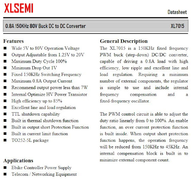 Limitations:
 LT3470 IC is used to design buck converter for the application having input voltage ranging from 4v to 40v and output voltage ranging from 1.25 to 16v@200mA. Application include automotive battery regulation and portable electronic devices. For more information in LT3470 refer the datasheet.
 However, MCP16331 can be used for applications requiring input voltage range 4.4v to 50v and output voltage range 2v to 24v@500mA. For more information refer MCP16331 datasheet. It is wide verity of applications that includes industrial DC/DC converter, automotive, and micro-controller supply etc.

Limitations:
- IC34063
- MP2307/MP2359
- XL7015
- ACT4088
- LT3470
- MCP16331
- LM2576/LM2576HV-12
1. MP2307 based Buck converter for 12 to 5V applicatons
This image shows a reference design for buck converter form 12v to5v application. This design shows few extra resistors at the output of converter, although they are not needed here. Full context of this design can be found here.

As the datasheet of MP2307 says, MP2307 can be used for the desing of buck converters for the input voltage ranging from 4.47v to 23v and output adjustable from 0.925v to 20v@3A. It can be programmed for soft start applications. It is widely used for making power supplies for battery powered applications.
MP2359 can also be used for the same purpose but it promises a bit lower current at the output. It's datasheet can be found here and a design example on chip is available at youtube. But this IC is a bit outdated.

- This design can work upto 23v input and 20v@3A output.
2. XL7015 based buck converter for 80v to 12v applications.
This design is for 80 to 12v buck conversion using XL7015. Full context of this design can be found here.

XL7015 based module can be purchased form Robu website.

- Input voltage 5v to 80v
- output voltage 1.25 to 20v@0.8A
- output power 7W
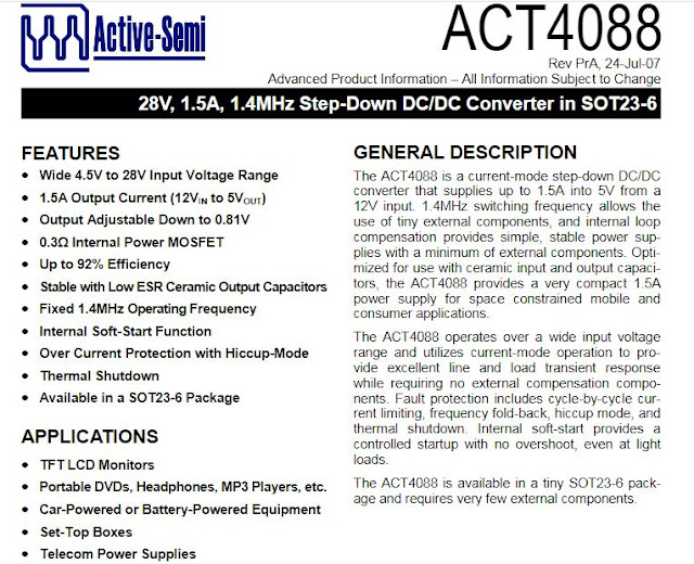
3. ACT4088 based buck converter for 12v to 5v application
A schematic design given below is designed for 12v to 5v applications. Full context of this desing can be found here.

However, following the datasheet, it is evident that ACT4088 IC is capable of working for input ranging from 4.5v to 28v and output ranging from 0.81v to around 20v. ACT4088 is capable of producing 1.5A for 12v to 5v applications. It is used for wide verity of battery powered applications.

Limitations:
- input range 4.5v to 28v
- ouput range 0.81v to around 20v
- output current 1.5A@12v to 5v conversion.
4. LT3470 based buck converter for 40v to 12v applications
A reference schematic design is given below and for more information on this design visit here.


Limitations:
- input range 4v to 40v
- output range 1.25 to 16v
- output current 200mA
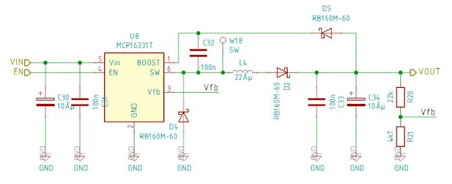
5. MCP16331 based buck converter for 12v to 5v applications
The schematic design given below is taken from cadlab.io website. This buck converter circuit is designed for around 24v to 5v applications.


- input voltage 4.4v to 50v
- output voltage 2v to 24v
- output current
- 1.2A@vout=3.3v or 5v when vin>12v
- 0.8A@vout=12v and vin>18v
Follow the respective datasheets for calculating the resistor, inductor, capacitor and diode values.
Comments
Post a Comment