- Get link
- X
- Other Apps
Introduction: Tachometer is used to measure the rotational speed of any rotating shaft or disk as in motor or any other machine that has rotating part. It is generally used to measure the RPM(run per minute) because RPM readings are used in the automotive(in throtle for speed control, in motor for rotor position feedback), aerospace, and manufacturing fields. Tachometers or revolution counters on cars, aircraft, and other vehicles show the rate of rotation of the engine's crankshaft, and typically have markings indicating a safe range of rotation speeds. In case of vehicle this can assist the driver in selecting appropriate throttle and gear settings for the driving conditions.
There are many types of Tachometers available in market but because of their high cost and size, they are not as common as the one we are going to make here using A3144. you can download its datasheet to see, how does it operate.
Hall Effect Sensor:
Hall effect sensors are semiconductor devices that allow the flow of current in proportion to the applied external magnetic field. Here, i will be covering the A3144 an inexpensive hall effect sensor. It is an unipolar sensor, meaning only one pole (either south or north) is sufficient for proper functioning. This enables us to glue a magnet on rotating object, and whenever, during revolution it passes the hall sensor, current flows in the hall sensor, and this is how, hall sensor indicates the presence of Magnetic pole. We use only one hall sensor for the RPM measurement, one crossing of magnet pole form the hall sensor will represent a complete revolution.
We will be using a 10k pull resistor between DAT and VCC pin to make sure the DAT pin is always high, when there is no magnet facing the hall sensor. This is because, whenever a pole faces the hall sensor it will be either at high/low depending upon which pole faces it. But, it is not always possible, that a magnet is facing the hall sensor, so this case the DAT pin will become floating. Hence to avoid this floating problem, we need to use a 10k resistor. so never forget to use a 10k pull up resistor.
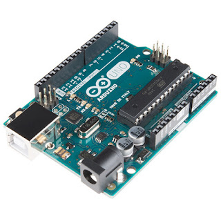
Connection with Arduino Uno:- Connect the pin-1 to the arduino uno 5V(make sure it is not below 4.5V and above 24V, for more follow the datasheet).
- Connect the pin-2 to Arduino Uno GND.
- Connect the pin-3 to Arduino Uno digital pin-2.
Now copy the below code to your Arduino IDE, and burn it into the Arduino Uno development board. Open the serial port monitor, and here you go.........your RPM is being printed on serial console
For any question feel free comment below...........


Comments
Post a Comment