- Get link
- X
- Other Apps
Introduction: In this post, first, the description about how to use the arduino as a USB to TTL converter and then we talk about how to use it to flash the STM32F1 Bluepill.
Why do we need a USB to TTL/ USB to UART/ USB to Serial converter?
Most of the processor including modern day ARM processors has inbuilt UART serial communication port that works on TTL logic level protocol for serial communication. The problem arises when we need to stablish communication between PC and processor, because most of the modern day PCs support only USB protocol for serial communication. Now, one has to fill the gap between these two protocols, and therefore, to solve this problem USB to TTL converters are utilized. This USB to TTL conversion can be done in two ways.
One, by directly using the USB to TTL converters with a normal connectors(they connect 5v, gnd, Rx and Tx of the the converter with corresponding levels at processor side).
Second, by using a max232 chip that converts the TTL signals to the RS232 signals along with a USB to RS232 serial cable.
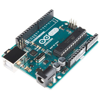
Converting an Arduino into a USB to TTL converter:
There are two ways to make an arduino board works as USB to TTL converter.
one is to Connect the RESET pin to the GND.
second to program the arduino by the following line of code.
void setup(){
pinMode(0,INPUT);
pinMode(1,INPUT);
}
void loop(){
}
In order to verify this second way, short the Rx and Tx pin of arduino board. Now, open the serial monitor and send text, if it is being echoed then USB to TTL converter is ready.
i will be covering the first method, but you could try the second method too.
Bluepill board:
Figure below shows the component description of Bluepill board.
Here, i will introduce you the different mode available in STM32F1 Bluepill board and the one we are going to use for our application of programming the Bluepill using Arduino.
Normal Mode: In this mode what ever the code placed inside of STM32F1 flash, it boots up and keeps running when it is powered on. For this mode use the boot jumpers as in the shown in the image.
Mode to upload the code directly to the RAM: In this mode, program is loaded to the RAM of STM32F1. but this mode has a problem that as the power is turned off, the code will be lost, it will no longer be available for the normal mode operation. Because, RAM is a volatile memory. put the jumpers as shown in the image to put the board in this mode.
System boot-loader mode: This is mode of our interest, in this mode the code will reside in flash memory that isn't volatile, and will be available for the normal mode operation even after the several on/off power cycle. For this mode use the jumper configuration as shown in the below image.
Utilizing the USB to TTL converter: In order to code the STM32F1 Bluepill board using arduino via UART, one has to connect these two board. Please follow the below connection details between the Bluepill and the arduino board.
Now download the flash loader demonstrator.exe from STMicroelectronics website or you can google it, run this exe file and select the .hex/.bin file from your project directory and upload it.
Conclusion: In this post i have covered that how to use an arduino board as a USB to TTL converter and thereafter i have demonstrated how to make connection between the STM32F1 BluePill board with Arduino board by the covering the different modes of operation available in the STM32F1 chip.
In case you are getting any problem please comment below.............


Comments
Post a Comment