- Get link
- X
- Other Apps
Interrupts:
- Allow the program to respond to events when they occur.
- Allow program to ignore events until they occur.
- External events
- UART ready with/for next character.
- signal change on pin.
- number of edges arrived on pin.
- Internal events
- Power failure
- arithmetic exception like dividing by zero.
- Timer "tick" (e.g., output compare match)
- ADC conversion complete
Uses for Interrupts:
- To detect pin changes (like: rotary encoders, button presses)
- Watchdog timer (like: if nothing happens after 8 seconds interrupt me)
- Timer interrupts used for comparing/overflow timers
- SPI data transfers
- I2C data transfers
- USART data transfers
- ADC conversions
- EEPROM ready for use
- Flash memory ready
In this tutorial we are going to be discussing more about the external and pin change interrupts than the internal interrupts.
External Arduino Interrupts:
- Using Arduino IDE
- Only 2 interrupts available INT0, INT1 (digital pins 2 and 3)
- can name interrupts arbitrarily
- able to use all 4 modes:
- LOW(ISR keeps on triggering as long the pin is in logic low state)
- CHANGE(ISR triggers when there is a falling/rising edge)
- RISING(ISR triggers when there is a rising edge)
- FALLING(ISR triggers when there falling edge)
- Using C, Assembly language
- able to use the 2 external, or 24 pin-change interrupts
- ISR names are predefined
- the pin change interrupts can only CHANGE mode
- can work with timers, counters, comm port, ..........
Example: Interrupts placement
- void setup(){
- attachInterrupt(0, Dr_ZAP_Int0, CHANGE);//on pin INT0 and hence first arg is 0
- attachInterrupt(1, Dr_ZAP_Int1, RISING);//on pin INT1 and hence first arg is 1
- }
- void Dr_ZAP_Int0(){
- //do what you need to do
- }
- void Dr_ZAP_Int1(){
- //do very important stuff
- }
Example: BLINK (every time there is a change on INT0 pin(digital pin-2), toggles the pin13 state.
int pin = 13;
volatile int state = LOW;
void setup(){
pinMode(pin, OUTPUT);
attachInterrupt(0, blink, CHANGE);
}
void loop(){
digitalWrite(pin, state);
}
void blink(){
state = !state;
}
The Interrupt Sequence: Interrupts are complex as compared to the other peripheral. Hence, it is a better practice to follow a fixed sequence while handling interrupts in Arduino Atmega328.
- void setup(){
- //instructions
- }
- void Dr_ZAP_Interrupts0(){
- //instructions for interrupt-0
- //no special return instruction needed.
- }
- void Dr_ZAP_Interrupt1(){
- //instructions for interrupt 1
- }
- void loop(){
- //main loop instructions
- //do stuff here that can be interrupted
- }
- float compute(int var){
- return (float)var*3.1415927;
- }
Arduino IDE interrupts:
- attachInterrupt() function
- detachInterrupt() function is used to detach the attached interrupt. Let say there is some attached interrupt at INT0(digital pin-2) and you want to disable it, then use the detachInterrupt() function with argument-0 (0: for INT0 and 1: for INT1).
- interrupts(): enables the interrupts to occur, meaning enables the global interrupt flag.
- noInterrupts(): disables all the interrupts to occur, except the reset interrupt
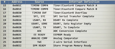
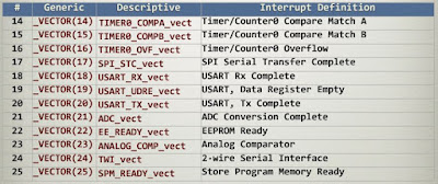
Atmega328 built-in interrupt Vectors:
- Interrupt handler must be invisible to program.
- except through side-effect, e.g. via flags or variables
- changes program timing
- can't rely on dead-reckoning
- con not stomp on program state, e.g. registers
- save and restore any registers used(including SREG)
- must be short and sweet
- Global interrupt enable
- Global interrupt enable bit is present in SREG
- Allows all interrupts to be disabled with one bit
- sei(): set the bit, same as interrupt() function
- cli(): clear the bit, same as noInterrupt() function
- Interrupt priority is determined by order in table shown above
- Lower addresses have higher priority
External Interrupts:
- monitors changes in signals on pins
- what causes an interrupt can be configured by setting the control resgisters appropriately.
- If there is a pulse coming on external input pins then pulses must be slower than I/O clock rate.
- INT0(PORTD digital pin2) and INT1(PORTD digital pin3) are the two external interrupts
- PCINT[23:0] pin change interrupts, there will be an external interrupts if any of these pin toggles. Remember that PCINT[15] is not available here, and PCINT[14] is reset pin.
- PCINT[7:0] at PORTB[7:0]
- PCINT[13:8] at PORTC[6:0]
- PCINT[23:16] at PORTD[7:0]
EICRA: External Interrupt Control Register A
EIMSK: External Interrupt Mask Register
EIFR: External Interrupt Flag Register
EIMSK's INT0 and INT1 bits are used to enable and disable the interrupt on INT0(D2 pin) and INT1(D3 pin).
Status register SREG:
It is possible to use pin change interrupts on "all" pins of the arduino using Pin Change Interrupt Requests. The example below uses some macros from the pins_arduino.h library.
The interrupt can be enabled for each pin individually (analog and digital!), but there are only 3 interrupt vectors, so 6-8 pins share one service routine:
- ISR (PCINT0_vect) pin change interrupt for D8 to D13
- ISR (PCINT1_vect) pin change interrupt for A0 to A5
- ISR (PCINT2_vect) pin change interrupt for D0 to D7
The interrupt fires on a change of the pin state (rising and falling).
- Get link
- X
- Other Apps


Comments
Post a Comment