Under progress..............
In order to download the proteus components library for proteus simulation follow the link..
Follow the youtube link lectures regarding the proteus installation and tutorials.
To avoid crashing your software while running the simulation follow the link.
A website to get more info about the proteus simulation.
A blog link for proteus motor simulation
While doing the schematics, avoid using the net

while simulating leds in proteus never forget to select the digital model instead of analog i.e. the default value, this can be done by clicking on the leds.
Project-1: LED blinking
- Basic code generation using STM32CubeMX
- For code editing, i am using here Keilv5
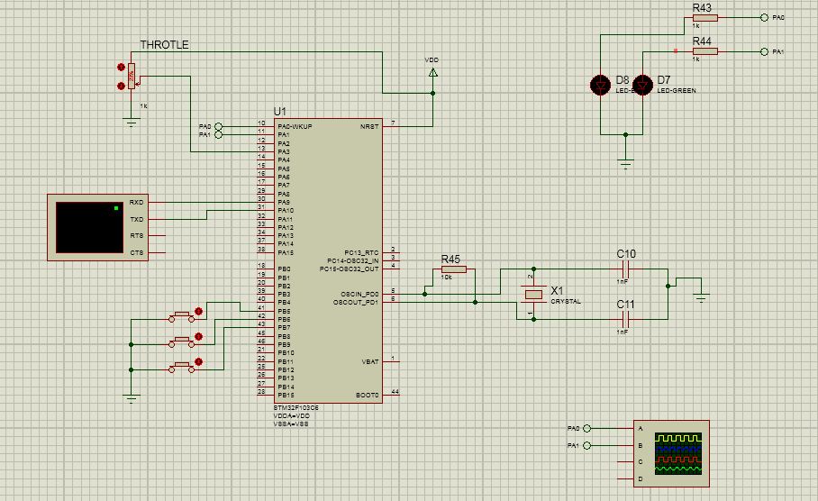
- For simulating it on Proteus using STM32F103C6 processor from STMicroelectronics


- HAL_GPIO_TogglePin(GPIOA,GPIO_PIN_0);
- HAL_Delay(10);
- HAL_GPIO_TogglePin(GPIOA,GPIO_PIN_1);
- HAL_Delay(10);
Project-2: UART


write the code
- char buffer[]="testing\n\r";
and in the main's while loop:
- HAL_GPIO_TogglePin(GPIOA,GPIO_PIN_0);
- HAL_Delay(10);
- HAL_GPIO_TogglePin(GPIOA,GPIO_PIN_1);
- HAL_Delay(10);
- //UART
- HAL_UART_Transmit(&huart1,(uint8_t *)buffer,sizeof(buffer),1000);
- HAL_Delay(10);
Project-3: ADC
ADC with DMA is not working on proteus, because proteus does not have model to support the DMA peripheral of micro-controller. Hence, here i will be using the ADC without using the DMA.


Global variables
- /* USER CODE BEGIN PV */
- char buffer[]="testing\n\r";
- char trans_str[64] = {0,};
- uint16_t adc[1] = {0};
- /* USER CODE END PV */
Code before the infinite while loop in main()
- /* USER CODE BEGIN 2 */
- HAL_ADC_Start(&hadc1);
- /* USER CODE END 2 */
Infinite while loop code
- /* USER CODE END WHILE */
- HAL_GPIO_TogglePin(GPIOA,GPIO_PIN_0);
- //HAL_Delay(5);
- HAL_GPIO_TogglePin(GPIOA,GPIO_PIN_1);
- //HAL_Delay(5);
- //UART
- HAL_UART_Transmit(&huart1,(uint8_t *)buffer,sizeof(buffer),1000);
- //HAL_Delay(5);
- //Reading channel 3
- HAL_ADC_PollForConversion(&hadc1,10);
- adc[0] = HAL_ADC_GetValue(&hadc1);
- snprintf(trans_str, 63, "throtle %d\n\r", (uint16_t)adc[0]);
- HAL_UART_Transmit(&huart1, (uint8_t*)trans_str, strlen(trans_str), 1000);
- //HAL_Delay(5);
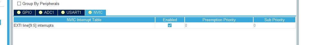
Project-4: EXTI
External pin interrupts are used to capture the output events


- /* USER CODE BEGIN Includes */
- #include "stdio.h"
- #include "string.h"
- /* USER CODE END Includes */
- /* USER CODE BEGIN PV */
- char buffer[]="testing\n\r";
- char trans_str[64] = {0,};
- uint16_t adc[1] = {0};
- /* USER CODE END PV */
- /* USER CODE BEGIN 0 */
- void HAL_GPIO_EXTI_Callback(uint16_t GPIO_Pin){
- HAL_GPIO_TogglePin(GPIOA,GPIO_PIN_1);
- }
- /* USER CODE END 0 */
- /* USER CODE BEGIN 2 */
- HAL_ADC_Start(&hadc1);
- /* USER CODE END 2 */
- /* USER CODE BEGIN 3 */
- HAL_GPIO_TogglePin(GPIOA,GPIO_PIN_0);
- //HAL_Delay(5);
- //UART
- HAL_UART_Transmit(&huart1,(uint8_t *)buffer,sizeof(buffer),1000);
- //HAL_Delay(5);
- //Reading channel 3
- //HAL_ADC_PollForConversion(&hadc1,10);//will be used in real hardware
- adc[0] = HAL_ADC_GetValue(&hadc1);
- snprintf(trans_str, 63, "throtle %d\n\r", (uint16_t)adc[0]);
- HAL_UART_Transmit(&huart1, (uint8_t*)trans_str, strlen(trans_str), 1000);
- //HAL_Delay(5);
Project-5: 3-PWM
Along with the three PWM signals, i have also implemented its control at PA6 pin. Using a button PA6 PWM generationg can be stopped/started. When the button is pressed: PWM will be ON else off.


- /* USER CODE BEGIN Includes */
- #include "stdio.h"
- #include "string.h"
- /* USER CODE END Includes */
- /* USER CODE BEGIN PV */
- char buffer[]="testing\n\r";
- char trans_str[64] = {0,};
- uint16_t adc[1] = {0};
- /* USER CODE END PV */
- /* USER CODE BEGIN 0 */
- void HAL_GPIO_EXTI_Callback(uint16_t GPIO_Pin){
- HAL_GPIO_TogglePin(GPIOB,GPIO_PIN_1);
- }
- /* USER CODE END 0 */
- /* USER CODE BEGIN 2 */
- HAL_ADC_Start(&hadc1);
- HAL_TIM_PWM_Start(&htim1,TIM_CHANNEL_1);
- HAL_TIM_PWM_Start(&htim1,TIM_CHANNEL_2);
- HAL_TIM_PWM_Start(&htim1,TIM_CHANNEL_3);
- /* USER CODE END 2 */
- /* USER CODE BEGIN 3 */
- TIM1->CCR1=100;
- TIM1->CCR2=200;
- TIM1->CCR3=300;
- HAL_GPIO_TogglePin(GPIOB,GPIO_PIN_0);
- //HAL_Delay(5);
- //UART
- HAL_UART_Transmit(&huart2,(uint8_t *)buffer,sizeof(buffer),1000);
- //HAL_Delay(5);
- //Reading channel 3
- //HAL_ADC_PollForConversion(&hadc1,10);//will be used in real hardware
- adc[0] = HAL_ADC_GetValue(&hadc1);
- snprintf(trans_str, 63, "throtle %d\n\r", (uint16_t)adc[0]);
- HAL_UART_Transmit(&huart2, (uint8_t*)trans_str, strlen(trans_str), 1000);
- //HAL_Delay(5);
Project-6:
ReplyDeleteSo nice I am enjoying for that post as for u latest version of this Security tool Available
kickasscrack.com
proteus-crack
restoro-crack
facebook-social-toolkit-crack
allavsoft-video-downloader-converter-crack
coreldraw-crack
ReplyDeleteAmazing blog! I really like the way you explained such information about this post to us. And a blog is really helpful for us this website.
Vstmania.co
Antares AutoTune Pro Mac Crack
Wilcom Embroidery Studio Crack
reFX Nexus VST Crack
Little Alterboy Crack
Native Instruments Kontakt Crack
Xpand Full Crack
Proteus Crack
Roland JV Crack
iZotope Ozone Advanced Crack
UVI Vintage Legends Crack
Waves Tune Real Time Crack
Soothe 2 VST Crack
SoundToys Crack
UAD Ultimate 10 Bundle Crack
Slate Digital Complete Bundle Mac Crack
Adobe Acrobat Pro DC Crack
I like your all post. You have done really good work. Thank you for the information you provide, it helped me a lot. I hope to have many more entries or so from you.
ReplyDeleteVery interesting blog.
kmplayer Crack
abelssoft-converter4video Crack
total-network-inventory Crack
proteus-pro Crack
ReplyDeleteVery good article! We will be linking to this particularly great post on our website. Keep up the good writing.
softcrack.org
DAEMON Tools Pro Crack
Total Network Inventory Crack
EFT Dongle Crack
FTP Rush Crack
EasyWorship Crack
Tekken Crack
FL Studio Crack
Wondershare Filmora Crack
iVCam Crack
Waves Crack
Wondershare Filmora Crack
SkinFiner Crack
Wondershare Filmora Crack
Amazing blog! I really like the way you explained such information about this post to us. And a blog is really helpful for us this website.
ReplyDeleteVstflex.net
GiliSoft Audio Toolbox Suite Crack
Total Network Inventory Crack
Miracle Box Crack
Fxpansion Geist Crack
Ultrasonic Martin Garrix Essentials Vol. 1 Crack
Sonic Academy ANA 2 Ultra Bundle Crack
Echoboy Crack
Waves 12 Bundle Crack
Abbey Road TG Mastering Chain Crack
Roland Cloud Legendary Aira Total Crack
Arturia V Collection VST Crack
Echoboy Crack
Sonnox Oxford Bundle Crack
VPS Avenger VST Crack
Roland Cloud Total VST Crack
I guess I am the only one who came here to share my very own experience.Guess what!? I am using my laptop for almost thepast 3 years,
ReplyDeletebut I had no idea of solving some basic issues.I do not know how to Download Cracked Pro Softwares
But thankfully,I recently visited is a website named Serial Link
Adobe Acrobat Pro DC Crack
OpenCanvas Crack
Anti-Porn Crack
Adobe Photoshop CC Crack
WinZip Pro Crack
Kutools for Excel Crack
I guess I am the only one who came here to share my very own experience. Guess what!? I am using my laptop for almost thepast 6 years, but I had no idea of solving some basic issues. I do not know how to Download Cracked Pro Softwares But thankfully, I recently visited is a website named startcrack.net/crack
ReplyDeleteGihosoft TubeGet Crack
Total Network Inventory Crack
Wondershare Streaming Audio Recorder Crack
Wondershare PDFelement Pro Crack
I like your all post. You have done really good work. Thank you for the information you provide, it helped me a lot. I hope to have many more entries or so from you.
ReplyDeleteVery interesting blog.
filecrk.com
abelssoft-converter4video Crack
ReplyDeleteHowever, stopping by with great quality writing, it's hard to see any good blog today.
https://crackpul.com/
Unity Pro Crack
AI RoboForm Enterprise Crack
TechTool Pro Crack
Articulate Storyline Crack
ImageRanger Pro Edition Crack
AOMEI OneKey Recovery Professional Crack
Proteus SP3 Crack
ReplyDeleteI am a professional web blogger so visit my website link is given below!To get more information
Total Commander Crack/
TechTool Pro Crack/
Fitness Manager Crack/
Kitchen Draw Crack/
Tenorshare 4uKey Crack/
Appreciation is a wonderful thing...thanks for sharing keep it up.Movavi Photo Editor Crack
ReplyDeleteImageRanger Pro Crack
NCH Debut Video Capture Crack
GoldWave Crack
4k Video Downloader Crack
Movavi PDF Editor Crack
iSkysoft Data Recovery Crack
Retail Man POS Crack
DisplayFusion Pro Crack
Corel Draw x7 Crack
AOMEI Partition Assistant Crack
Helium Manager Premium Crack
CloneDVD Ultimate Crack
MiniTool Power Data Recovery Crack
Adobe Photoshop CC Crack
EarthView Crack
Avast Secure Browser Crack
Call of Duty Black Ops Crack
Blackmagic Fusion Crack
Soundop Audio Editor Crack
Advanced SystemCare Pro Crack
MiniTool Partition Wizard Crack
Ashampoo Music Studio Crack
ViewCompanion Premium Crack
PDF To Excel Converter Crack
Wondershare MobileTrans Pro Crack
Wondershare Recoverit Crack
PC Cleaner Pro Crack
Movavi Video Editor Plus Crack
ABBYY FineReader Crack
Thanks For Post which have lot of knowledge and informataion thanks.... Adobe Photoshop CS6 Crack
ReplyDeleteLennar Digital – Sylenth1
Video DownloadHelper Crack
Waves Complete Crack
Proteus SP1 Crack
reFX Nexus Crack
NCK Dongle Crack
UAD Ultimate Crack
SolidWorks Crack
Lightburn Crack
CRACK SOFTWARE WITH PATCH AND SERIAL NUMBER
VST Plugins Crack Direct Download
IDM Crack
https://pcproductkey.org/
This site have particular software articles which emits an impression of being a significant and significant for you individual, able software installation.This Download Latest PC Cracked Softwares is the spot you can get helps for any software installation, usage and cracked.
ReplyDeleteproteus-crack