- Get link
- X
- Other Apps
This Blog is just for my own learning purpose, and at the same time i think it might be helpful to someone who is also interested in learning freeRTOS using Arduino IDE. I am open to suggestions, and hence feel free to comment below. For any reference and documents you can visit my post here.
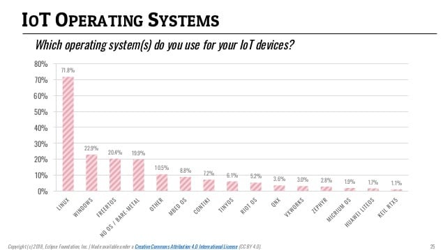
Before learning about how to write code using freeRTOS, one should first know why to learn the freeRTOS at the first place. Some of the images are given to understand the need of freeRTOS as compared to the other programming paradigm.
 |
| Different Linux distributions used in IOT. |
 |
| IOT Operating system for resource constrained devices |
 |
| IOT Operating systems for general devices. |
From the above three figures it must be clear now why do we really need the freeRTOS. Now the different concepts of freeRTOS is discussed here and are divided into many examples. So i would recommend reading each examples carefully.
Example-1: LED-Blinking, Time measurementIn this example, a very simple code is taken for demonstration. An LED at pin13 of Arduino Uno is blinking at every sec and processor on-time is measured.
#include <Arduino_FreeRTOS.h>

// define two tasks for Blink and AnalogRead
void TaskBlink();
void TaskClock();

// the setup function runs once when you press reset or power the board
void setup() {

  // initialize serial communication at 9600 bits per second:
  Serial.begin(9600);

  while (!Serial) {
    ; // wait for serial port to connect. Needed for native USB, on LEONARDO, MICRO, YUN, and other 32u4 based boards.
  }

  // Now set up two tasks to run independently.
  xTaskCreate(
    TaskBlink
    ,  "Blink"   // A name just for humans
    ,  128  // This stack size can be checked and adjusted by reading the Stack Highwater
    ,  NULL
    ,  2  // Priority, with 3 (configMAX_PRIORITIES - 1) being the highest, and 0 being the lowest.
    ,  NULL );

  xTaskCreate(
    TaskClock
    ,  "Clock"
    ,  128  // Stack size
    ,  NULL
    ,  1  // Priority
    ,  NULL );

  // Now the task scheduler, which takes over control of scheduling individual tasks, is automatically started.
}

void loop()
{
  // Empty. Things are done in Tasks.
}

/*--------------------------------------------------*/
/*---------------------- Tasks ---------------------*/
/*--------------------------------------------------*/

void TaskBlink(){
  // initialize digital LED_BUILTIN on pin 13 as an output.
  DDRB |= (1<<5);
  for (;;){
    PORTB ^= (1<<5);
    vTaskDelay( 1000 / portTICK_PERIOD_MS ); // wait for one second
  }
}

void TaskClock(){
  static uint32_t t;
  static uint8_t k=-1;

  for (;;){
    uint16_t getTick = xTaskGetTickCount();
    if(getTick < 10)k++;
    t = (((uint32_t)65535*k+(uint32_t)getTick) * portTICK_PERIOD_MS)/1000;
    Serial.print(t/60/60);Serial.print(":");Serial.print((t/60)%60);Serial.print(":");Serial.println(t%60);
    vTaskDelay(10);  // one tick delay (15ms) in between reads for stability
  }
}
Once the code is burned into the Arduino Uno board(if the code is successfully burned then the on-board aruduino uno led starts blinking) connect it to the PC and open the serial monitor to see the ouput: OUPUT FORMAT: HH:MM:SS.
Example-x: Software I2C
I2C is a two wire communication protocol that is widely used in display devices like OLED SSD1306. Microcontroller on Arduino Uno board has hardware I2C available at A4 and A5 pins. But, sometimes these pins are already busy or you don't want to use these pins at all. In such cases, software I2C is implemented.
To gain more clarification lets take another example on software I2C: Lets say you want to interface AT24C256 EEPROM and OLED SSD1306 with the Arduino Uno. Now, here is the problem because both these interfacing devices use I2C protocol for data transfer and Arduino has only one hardware I2C available. To overcome this problem one I2C for the external EEPROM memory should be implemented using the software I2C at some other pin pair on Arduino Uno board.
Example-x: External Interrupts, RPM counter.
Example-x: ADC
Example-x: OLED SSD1306 display.
Example-x: Push button implementation.
Example-x: External EEPROM
Example-x: PWM
Example-x: Interrupts
Example-x: Different boot-up modes.
Example-x: SPI, I2C, USB, UART, RS232, RS485, Ethernet CAN-bus


Comments
Post a Comment