AVR-I

Programming ATmega328 in Assembly using Arduino IDE and Arduino Uno Development Board

L1........

What is an Embedded System?

It is an integration of Sensors, Actuators and Intelligence with a system to produce more capable, versatile and robust performance.

When to use a microcontroller?

Microcontroller is used when:

  • Intelligence is required in the system.
  • the complexity reduction of a system is needed.
  • Once has to reduce the system design cost.
  • A variety of sensors and actuators must be integrated in the system.
  • Communication with other devices is necessary.

We will using C/C++/Arduino/Assembly language for higher speed functins/FPGA for highest speed(VHDL).

Microcontroller Manufacturer

  • AMCC
  • Atmel
  • Comfile Technology Inc.
  • Coridium
  • Cypress Microsystems
  • Dallas Semiconductor
  • Elba Corp.
  • Freescale Semiconductors
  • Fujitsu
  • Holtek
  • Infineon
  • Intel
  • Microchip Technology
  • Natinal Semiconductor
  • NEC
  • Parallax Inc.
  • Philips Semiconductors
  • PICAXE
  • Renesas Technology
  • Silabs
  • Silicon Motion
  • STMicroelectronics
  • Texas Instruments
  • Toshiba
  • Western Design Center
  • Ubicorn
  • Xemics
  • Xilinx
  • ZiLOG

Assembly language is main topic of discussion here, because it performs really fast and very good for time critical operations.

L2........................

Other than Microcontroller there are some other SOC that implies intelligence, so here, some comparison is done between

  • uC vs ASIC
  • uC vs CPLD
  • uC vs DSP
  • uC vs FPGA
  • uC vs PLC
  • uC vs uP

and the comparison is based on the following features...

  • Computational Power
  • Ease of programming 
  • Speed of Operation
  • Interrupts
  • Ease of Interface(analog and digital)
  • Overall system cost
  • Reconfiguration(How easy to configure for other tas)
  • Versatility(How many other tasks it can be configured for)
  • Communication with other devices
  • Timer/Counter Functions
  • Handing Media
  • Overall time required(the time required to start working with it for the first time).

Follow the website for different available Arduino Uno shields

Arduino Yun has the same basic arduino along with linux core that can run linux OS.


Arduino Uno Overview


GPIO

  • can be used as input or output
  • Each pin can be uniquely assignable
  • Analog(PWM) output on digital pins 3,5,6,9,10,11
  • Analog pins 0-5 can also be used as GPIO
  • Pull Up resistor with every GPIO pin is present

Digital Inputs:


Pull up resistors are used to avoid the floating pin problem. when the button is pressed GND will be detected at the input pins and when unpressed it is 5V. If we dont use the pullup resistor and connect the point directly to the 5V it will burn the uC because of high current sinking into the uC.

In this case we can use internal pull resistor but it need more info about the input port but we will see it later.

Analog Inputs:

  • Takes a continuous valued input signal from 0-5V, it can be from any sensor.
  • Assign the input a value from 0-1027.


Let say the input signal is coming from cruise control or techometer, you need to be careful that the input signal must not go too beyond the 5V level else it will damage the Arduino. Arduino quantize these voltages in a value from 0-1027. Whenever we are reading the analog value it is always instantaneous. Think about aliasing here, that it is going to effect the reading while sampling.

Analog(PWM) Output:

Analog output is produced by means of generating the PWM signal, varying the duty cycle varies the output voltage between 0-5V.

Software comparison that are used to develop code for Arduino

This table gives an idea what tool you should be using for your project. If your application is speed critical then use ASM language. Although, for applications that doesnt need too much speed but needed less development time then you should go for Arduino IDE.

In order to utilize the each and each function of microcontroller assembly is used here. There are some features that cannot be used with the use of Arduino IDE like: internal temperature of Atmega328, 10bit PWM.


Arduino IDE/C/C++/ASM develops the brain of Arduino Uno development board.


Arduino IDE will be used here to develop the c/c++ and assembly by modifying the Arduino IDE because standard Arduino IDE doesnt support Assembly language. However, it supports the c/c++ language.

L3....................

Here  will be focusing on Arduino IDE, one can use processing either.

Arduino IDE is based on C/C++. In Arduino we are gonna be using two function 

  • void setup(), where you are do all the necessary setup that are needed to be executed once
  • void loop(), you need to write the part of code that is required to be executed forever

In case you want to brushup you programming skills in C, please click on the link...

Now, you will be writing the very first code using Arduino IDE that does nothing and compiles perfectly.


For more details about how and which function used, please follow the link..

Arduino IDE: Constants
  • Before using a GPIO pins as input/output, one has to configure the GPIO pins as input/output by writing INPUT/OUTPUT and for using the internal pullup resistor one has to write INPUT_PULLUP.
  • Once the GPIO pin is configured as input/output, Now, you can write 1/0-logic to your digital pins, by writing HIGH/LOW. 
  • In C/C++ 0-integral value represents the boolean false and non-0 positive integral values represents the boolean true. But, here in embedded programming, most of the time you are going to do the same thing by writing true/false constants.
  • a program is does nothing but the modifies the data in the memory in order to produce the useful data, for a program to do so, a programmer should know how to enter those numeric data into the program. For this purpose, IDE defines how to write these values like: writing B11010101, -123, 123uL and 0x123 will be treated as Integer. While -1.2, 1.75e5, -62E-12 will be treated as floating point values. Check whether 12. and 12.0 are treated as integer or float.
Data Types


  • c indicates that there is a conversion function for type-casting
  • word is similar to the unsigned int but it has type-casting function
  • boolean contains only 1-bit of data but takes 8 bits in memory
I/0 Functions:
  • pinMode is a function that can be used for the given pins and can be used as INPUT, OUTPUT, INPUT_PULLUP.
  • tone() is used to generate a certain frequency signal, namely PWM with 50% duty cycle.
  • noTone() is used to stop the toning.
  • pulseIn() measures the pulse width of incoming signal.
  • By default the reference voltage for ADC is 0-5V but it can be settled to 0-3.3V etc.
  • analogRead returns 10bit number
  • analogWrite takes 8 bit number
Interrupts:
  • attachInterrupt to a particular pin and takes the routine name to process
  • detachInterrupt from a particular pin
  • interrupts() to enable the  interrupts, meaning allows the interrupts to happen
  • noInterrupts() stops the process from being happen
BITS and BYTES:
  • lowByte
  • highByte
  • bitRead
  • bitWrite
  • bitSet
  • BitClear
  • bit
Communications over TWI(two wire communication like: USB, UART):
  • shiftOut 
  • shiftIn
  • Serial is a class with the following functions

(Serial) is not a function but it returns-1 when the serial port is ready while 0 for not ready.

Available Functions:

Operators:

flow controls:

Speed comparison between the code developed in c/c++ and the code developed in Arduino IDE:
Here, i will be talking about the two codes: one code is written in Arduino IDE using arduino library and the other is in Arduino IDE but using C/C++. The code is to blink an LED as fast as possible, although our eyes cannot detect this blinking but for the purpose of execution time period comparison, it is the best option.
while loop is far faster than the loop, hence in C/C++ example while is used. Using this method of blinking an LED is fastest possible way and it blinks the LED at 2.66 MHz of frequency while using Arduino IDE the blinking frequency is 121 KHz.


Now, we will be looking at how long a function takes to execute in Arduino IDE
  • All the delay function in Arduino IDE are not accurate look at the last entries of the table below.


Serial Communication:
  • fifth line in the code while(!Serial) checks whether the serial port is available for the service or not.

Latency: Meaning, how long a message takes while being transmitted serially
  • If we send 0-40 bytes of data over serial port it takes around 4ms but for 40-80 bytes of data it takes around 8ms.
  • In conclusion, Arduino takes at least 4ms to send any byte through the serial port.
The figure below is the rate of data transfer: Means, how fast the data is being transferred. 
if we want to send 50 bytes of data, the bandwidth we will get is around 5Kbps.
L4...............

Now, i will be talking about: when it is appropriate to use a micro-controller among the options available like:
  • ASIC (application specific integrated circuit)
    • This is not the general purpose, meaning we cannot modify the way we wanted.
    • There are two types of ASIC: one is Fully-Custom(all layers are optimized for a specific application) and the other is Semi-Custom( bottom layers are optimized but top layer is available for to customization.
    • Hence, ASICs are very-very fast but not flexible because it gives a little bit of flexiblity.
  • CPLD (complex programmable logic device_)
    • It is in between PAL and a FPGA
    • it consists of lots lots of gates for the customization.
    • it has non-volatile memory
    • fast and flexible
  • DSP (digital signal processor)
    • designed for signalling operation
    • designed around IO(digital/analog)
    • May include:
      • Quadrature decoder(used for rotary position decoding purposes)
      • PWM
      • serial communication
  • FPGA (Field programmable gate array)
    • large interconnection matrix, logic gates, RAM
    • mostly has ADC and DAC
    • programmable by computer
    • highly flexible
  • PLC (programmable logic controller)
    • designed for industrial applications
    • it uses alot of relays
    • very broad range of capabilities 
    • often programmed graphically
  • uP 
    • very fast at math processing capability
    • designed with certain peripheral
    • significant memory
    • runs an OS
    • my be single board
  •  uC
    • wide verity of Arduinos
    • Make Controller
    • PICAXE
    • BASIC stamp
How do choose the uC?
  • Define the system requirements like:
    1. Computational power
    2. Ease of programming
    3. Speed of operation
    4. Interrupts
    5. reconfiguration
    6. power/heat
    7. interfacing/compatibility(is it compatible with CMOS/TTL or not)
    8. overall cost
    9. versatility
    10. communication with other devices
    11. safety
    12. upgradability
    13. memory
    14. timer/counter function
    15. handing media
    16. overall time required to assemble
    17. EMI/EMC
    18. size
    19. availability
  • Choose the processor technology
  • List all good candidate
  • finalize the selection
L5...........

Interfacing:
Here i will be talking about how to interface the uC with the outer world. Mostly in embedded systems the two interfacing circuit's characteristics are not compatible, Hence, a circuit needs to be inserted in between the two devices for the proper operation


i will be covering here
  • Circuit Basics
  • Basic circuits
  • opamp circuits
  • digital interfacing
  • analog interfacing
  • power interfacing
Arduino voltage characteristics:
  • operating voltage: 5V
  • Recommended Input Voltage: 7-12V
  • Extreme Input Voltage: 6-20V
  • Max voltage applied to any I/O pin: 5.5V
  • Max voltage applied to any 5V pin: 6V
  • Max voltage applied to 3.3V pin: 3.6V
  • Max voltage applied to Reset pin: 13V
Arduino current characteristics:
  • Max current on any I/O: 40mA
  • Max current sourced from any I/O: 20mA
  • Max current from VCC pin: 200mA
  • Max current from each GND: 200mA
  • Recommended steady state current: 1/2 of the max rating
Arduino Resistance characteristics:
  • Internal pullup resistor: 20k
  • steady state load resistance(recommended): 470E to 10K
  • High impedance input state resistance(when a pin is configured as input): 100M ohms
EXAMPLE-1: Now, let say we have a sensor signal that outputs +-10V and we need to interface it with arduino uno that has 0-5v operating range at analog pin. we will see how to make an interfacing circuit.


s(t) is the signal coming from the sensor, and we need to scale and shift it to make it compatible with arduino 0-5v. so we need to transform +-10v to 0-5V range.
S0= -10v and S1= 10V and we need to find out the K and b, that can be found using formula given below that works for Arduino

Implementation of shifting and scaling circuit:
  • left opamp is working as a shifter and the right opamp is doing the scaling
  • S2 is the supply voltage, that is equal to positive opamp biasing voltage
  • choose the resistor value using the equation below

EXAMPLE-2:
Reading an analog voltage using potentiometer
if we move the wiper all the way up then there will no resistance, while full 5k resistance is present in case the wiper is all the way down. Loading effect cannot be seen here because of the high input resistance of the pin configured as input.


Analog Outputs:
  • PWM
    • There are two types of PWM signal Unipolar and bipolar

    • Arduino has only unipolar PWM signalling
    • Bipolar is used mostly in motor that can run in either direction
  • R-2R Ladder network

  • DAC chips/shield
  • Hack-method follow the link..
Low pass filter: will eliminate all the frequency below the f, it doesn't effect the signal amplitude level but it filters the noise present the signal. The filter below is called as active filters because the passive ones doesn't works as well as active.


Digital Interfacing:
If the digital signal is at the TTL level then it can be directly connected to the micro-controller. However, mostly, the real life signals are analog, and these signals are susceptible to noise like ESD, spikes, lightening strikes etc and hence to avoid these noises entering the processor we use optoisolators. Optocouplers are commonly used in automotive industry.

Pull up resistors:


Switch debounce hardware: when we press a mechanical switch, its level doesnt get stable in single go, but it oscillates between a range of voltage values first, then gets stable, hence this problem is called as switch debounce problem. However, this doesnt happen in optical switches.

In order to avoid this debounce problem the two methods are used: one is by means of using a low pass filter and shmidt trigger, other is using the logic gates. The low pass filter removes the debounces and then the signal passes to the shmidt trigger that is a bit slow circuit and hence what ever the input debounce comes, gets estabilished by the shmidt trigger, then the cleaned signal goes to the uC.


CMOS vs TTL: CMOS is one form of digital technology and TTL is also a form of digital technology but different from CMOS, lets look how these two technologies are different from each other so that their interfacing problem with each other can be resolved. Their logic levels are defined below.
  • In TTL, 0-0.8 is considered as logic low during input to TTL circuit. However, 2-5V is considered as logic-high during input to TTL circuit.
  • When TTL circuit writes high to a pin it can be anything from 2.7v to 5v, although, for low it is 0-0.5v
  • similarly one can see for CMOS
  • CMOS is very good for switching
  • CMOS is necesserily be between 0-5v, but it can any voltage higher than 5V like: 10V and so


Arduino digital I/O pins are TTL Compatible.

TTL to CMOS conversion circuits:


CMOS to TTL conversion circuits:
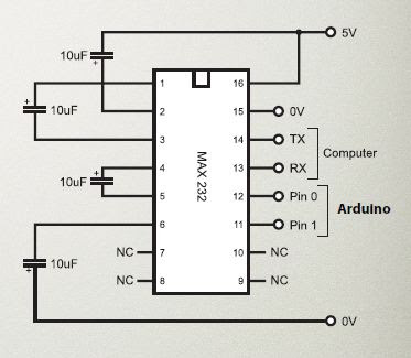
TTL to RS232:
  • RS232 is an old serial communication standard but still being used quite a lot.
  • typical voltage values for RS232 are +-15V, but it could be +-25V.

Power Interfacing: power interfacing can be done using relay switching through the use of a transistor being switched from uC.

Human reaction time is around 10Hz.


L6.......................

Comments