In this tutorial we will be talking about the richest topic "Timers/Counter".
We are using the timers without knowing about them, this is because arduino IDE is very good at hiding contents from the users, like:
- The millis() and micros() functions: timer0
- The analogWrite() function
- The Tone library
- The servo library: timer1
Timers/Counters

- Timer-1,2 set ready for analogWrite() PWM use
- set to 8bit PWM phase-correct, with the clock prescaled to the system clock divided by 64..
- Timer0 set to fast PWM for use with the millis()/micros()
Control Registers
- Timer/Counter control register A: TCCRnA
- Timer/counter control register B: TCCRnB
- Timer Count: TCNTn (is 16/8 bit depending upon the timer/counter is 16/8 bit)
- Output compare register A: OCRnA
- Output compare register B: OCRnB
n is 0,1 or 2 for Arduino Uno
nth Timer/counter Block diagram

Timer-0
- most used timer in applications
- Can be used as:
- simple counter
- frequency generator (inc. PWM)
- External source clock counter
- Able to generate "tree" interrupts
Tree interrupts on TC0:

A timer is a counter with a clock input
PWM modes:

the center of PWM pulse is in phase with the triangular wave in phase correct PWM.
- Normal mode: Counter counts up to MAX(0xFF), then resets to 0
- Phase correct PWM mode: PWM that is synchronized so that it is symmetric with respect to the timing clock.
- Clear Timer on Compare(CTC) mode: the output of the counter is continuously compared with an output compare register. A match can be used to generate an interrupt
- Fast PWM mode: PWM that goes as fast as the clock will allow. Not synchronized with the timing clock.
Timer/Counter control register (TCCR0A):
- The COM0x bits, controls the behavior of the output compare pins OC0A and OC0B
- The WGM0n bits, controls the function of the output compare pins OC0A and OC0B


In the above figure, there are two possible ways to generate the Phase correct PWM, it seems like they are same but no, they are not. First, when WGM0-2:0 is 001 then the top value is 0xFF for the counter , while OCR0x update takes place when counter reaches to the TOP and TOV0 set to 0x00. Second and lastly, When WGM0-2:0 is 101 then the top value is set by the OCR0A registor and the OCR0x register gets updated when counter reaches to the top and the TOV0 set to the 0x00.
Compare output mode T/C-0 bits Under different Modes:


T/C-0 Control Register B:


- 001-div by 1
- 010-div by 8
- 011-div by 64
- 100-div by 256
- 101-div by 1024
Clear Timer On Compare Match(CTC):
- WGM=010
- CTC clears with respect to OCR0A, not OCR0B
- Thus, OCR0A sets the timing, but OCR0B can still be used
- Setting the frequency, when using a toggle means you have to halve the period to get the correct frequency.
Example: Now we will discuss about the real life example that involves the Timer/Counter and that is nothing but Quadrature encoder simulator
problem: Create a 500 pulse per revolution quadrature encoder simulator that outputs quadrature signals out on pins from timer-0. Assume the rotation is a constant speed of 10 rev/sec.
Hence, 500 ppr * 10 rev/sec = 5000 pulse per second. i. e. 5KHz. This corresponds to a period of 0.2ms, that toggles every 0.1ms as shown in the figure below.
 |
| Showing the signal with 0.2ms period |
Working Theory: Quadrature encoder has two emitters and two detectors to detect the signals coming from the emitters. The signals that come from the emitters are blocked by the rotating disc and in this case corresponding detector detects no signal that results in a logic-0, and logic-1 when it detects the signal. The waveform in blue color is drawn on the basic of signal detected/blocked by the detectors.
As we have seen that every 0.1ms we need 2 toggles in the signal level. Its time to select the frequency prescalar to get the desired toggle rate. It is evident from the figure, that at different clock select there is a different prescalar, frequency and period. The last column shows how many clock pulses are there in 0.1ms time period.
Now, how to select one, it depends on how much accuracy you want in waveform generation: the more number of clock pulses in 0.1ms the more accurate the signal waveform will be.
problem in choosing low number of pulses per 0.1ms: if we are off by one count and the number of pulses chosen is 200 per 0.1ms then there will be 1/200*100=0.5% error in timing of output waveform, but if we choose 25 then there will be an error of 25% in output waveform.
 |
| Clock Select |
For our case we will be using 200 pulse per 0.1ms to maintain its accuracy. we could have chosen 1600 pulse per 0.1ms, no problem but this number is a 16bit number while 200 is just an 8bit number.
Timing Diagram: Figure demonstaretes how the timer is counting up and resets back to zero when matched to OCR0A.
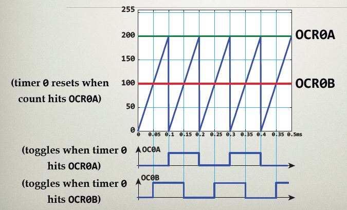 |
| Timing Diagram |
Register and values:
- OCR0A: 200
- OCR0B: 100
- COM0A: 01 (TCCR0A)
- COM0B: 01 (TCCR0A)
- WGM0: 010 (TCCR0A and TCCR0B)
- CS: 010 (TCCR0B)
Now coming to the actual code:
- void setup(){
- PORTD &= 0b10011111;//setting pin 5, 6 to zero
- DDRD |= (1<<6)|(1<<5);//setting pin 5,6 as outputs
- //initializing the timer in CTC mode and setting PD5 and PD6(OC0A, OC0B) to toggle
- TCNT0 = 0;
- OCR0A = 200;
- OCR0B = 100;
- TCCR0A |= (1<<COM0A0)|(1<<COM0B0)|(1<<WGM01);
- TCCR0B |= (1<<CS01);
- }
- void loop(){
- }
NOTE:
- It is always a good practice to initialize the pins before setting their direction as it is done in line second and third, although initialization is not necessary
- If we dynamically update the OCR0A values then the PWM frequency will by changed and SPWM can be generated this way.
Timer Counter Registers:

PWM PINS:
- TIMER0---->8bit--->OC0A(PD6),OC0B(PD5)
- TIMER1---->16bit--->OC1A(PB1),OC1B(PB2)
- TIMER2---->8bit--->OC2A(PB3),OC2B(PD3)

FAST PWM MODE:
- This mode produces the fastest PWM waveforms (compared to phase or phase and frequency correct).
- The timer counter TCNTn simply counts from BOTTOM(0x00) to the TOP(0xFF or 0xFFFF) and then resets.
- When TCNTn reaches the output compare (OCRnA or OCRnB), the output compare bit (OCnA or OCnB) is cleared. These are then set when the TCNTn rolls over.
 |
| FPWM |
Example:
- Use fast 8bit PWM
- Use both A and B on timer0
- Clear the output compare bits on compare match, set on TOP
- Choose a PWM frequency approximately twice the default PWM frequency(approx 1Khz).Default PWM is defined as the frequency of PWM signal generated using analogWrite() function from Arduino library in a fastest way possible and i.e. equal to approximately 500Hz.
- The humming sound is directly proportional to the frequency of PWM signal that you are using for motoring application. If we use 1Khz of frequency then its humming sound will be more as compared to the higher frequencies of the order of 10kHz. This is the reason why most of the industrial motor controller uses the PWM signal of frequency around 16KHz so that the humming sound from the motor is not audible to the user.
Using fast PWM the frequency selection can be made on the basis of prescalar as discussed earlier. Table below shows the frequency that can be achieved at different prescalar while using fast PWM.

Registers and values for the above problem:
- TCNT0: 0
- COM0A: 10
- COM0B: 10
- WGM0: x11
- CS: 011
code:
- void setup(){
- PORTD=0x00;
- DDRD= (1<<5)|(1<<6);
- TCCR0A=0b10100011;
- TCCR0B=0b00000011;
- TCNT0=0;
- }
- void loop(){
- OCR0A=128;//to set the duty cycle for channel A
- OCR0B=64;//to set the duty cycle for channel B
- }
Phase Correct PWM:
- produces symmetric wavefroms, which provides smoother motions when used in motor applications.
- The center of each pulse occurs at the period, as opposed to the falling edge on the period.
- Up/Down counter required.
- frequencies are half of that used for fast PWM.


Click Next to study about ADC in Atmega328 microcontroller.
Comments
Post a Comment